
Part 1 of this series can be read here. In this part, the following topics are discussed.
- Governing documents
- Piping class structure
- Typical piping components in a piping class
- Required information for components
Governing Documents
A piping class concisely captures the requirements regarding design, materials, fabrication, examination, inspection and testing of piping systems from applicable acts and regulations (Federal, Provincial/State), design codes, company standards and practices, and industry best practices. The order of precedence among different sources of governing requirements for a piping class is shown in Figure 1. “Acts and Regulations” are the foundational requirement documents followed by “Industry Codes and Standards”, “Company Standards and Practices” and so on. The designer of the piping class, and to some extent, the user of the piping class must understand the relationship between governing requirements to ensure the correct application of the piping class to the design of the piping systems.
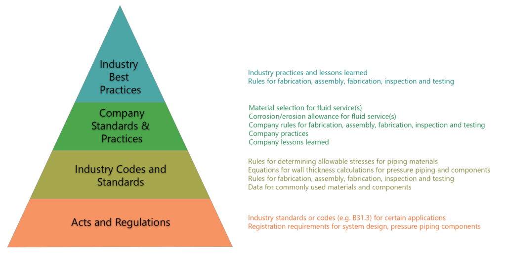
Figure 1: Order of Precedence in Governing Documents
Piping Class Structure
The presentation of a piping class’ content can vary between organizations. A piping class typically consists of five sections as noted below.
Table 1: Piping Class Sections
| Section No | Section Name | Location | Criticality | Details |
| 1 | Header | Integral | Required | This section contains piping class level information such as piping class name, fluid services for which the piping class is compatible, temperature/pressure limitations, welding requirements such as PWHT, examination requirements, and pressure testing requirements. |
| 2 | Body | Integral | Required | This section is the heart of the piping class and lists pipe, fittings, flanges, valves and other components permitted in piping class. This section is presented in tabular form. If a component is not listed in this section, its use is not allowed under the piping class. |
| 3 | Branch Connection Table | Variable | Required | This section is a lookup table that defines permitted branch connection type for a given header and branch size. In some cases, more than one branch type is permitted for a header/branch size combination. In this case, the user of the piping class shall determine the branch connection type to be used. |
| 4 | Fitting Table | Variable | Optional | This section defines the permitted size combinations in the piping class for fittings with two different inline sizes such as reducers and swages. This section is often omitted in the piping classes. Most piping class authors try to cover the permitted size combinations for these different inline size fittings in the piping class body. However, this approach often leads the user of the piping class to interpret/select the size ranges. |
| 5 | Notes | Variable | Required | This section provides the text for all the notes called out in the header and body of the piping class. |
Where
Integral: This section is always part of the piping class.
Variable: This section can be part of the piping class or can be a standalone section that is referenced in the piping class.
Required: A piping class is not complete without this section.
Optional: This section can be omitted in the piping class.
Section 1 and 2 are mandatory sections of a piping class. Section 3 to 5 can be part of the individual piping class or can be independent sections/documents shared across multiple individual piping classes. Structure of a typical piping class is shown in Figure 2.
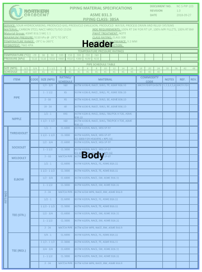
Figure 2: Basic Structure of a Piping Class
Components in the Piping Class
Straight pipe is the primary and central component of the piping class. Other components can be categorized as listed components and unlisted components.
Listed Components
For these components, the applicable design code or one of the referenced (in the design code) component manufacturing standards has the rules to determine the pressure rating of the component without additional calculation or testing. For example, ASME B16.9 standard for butt-weld fittings is a listed standard in ASME B31.3. ASME B16.9 para 2 provides guidance on the pressure rating of the butt weld fittings. Therefore, except special cases noted in the manufacturing standard, any component manufactured according to ASME B16.9 does not require additional calculation or testing to determine the pressure rating of the component.
Group A: Components with Pressure Ratings Derived from Selected Pipe Wall Thickness
The underlying assumption for the basis of the component pressure rating is that pipe and component are made from an equivalent material (as shown by comparable composition and mechanical properties). Once the pipe wall thickness is selected for a given design condition, the wall thickness or pressure rating of these components can be determined based on the wall thickness of the adjoining pipe. Some examples of these fittings include the following:
-
- ASME B16.9 Factory-Made Wrought Buttwelding Fittings
-
- ASME B16.11 Forged Fittings, Socket-Welding and Threaded
- MSS SP-97 Integrally Reinforced Forged Branch Outlet Fittings – Socket Welding, Threaded and Buttwelding Ends
Group B: Components with Independent Pressure Ratings
For these components, the design code has specific design equations or have referenced standards with published pressure ratings. In both cases, the wall thickness and pressure rating of the component cannot be determined based on adjoining pipe wall thickness. Some examples of such components include the following:
-
- Flanges
-
- Closures
-
- Blind flanges
-
- Blanks
-
- Gaskets
- Special fittings such as reinforced branch connections or extruded outlet header
Group C: Components with No Ratings
Some components have no defined pressure rating. One example of such components is bolting used for flanged connections.
Unlisted Components
For these components, the design code does not provide component-specific guidance, or there is no component manufacturing standard available. Also, if a listed component falls outside the limits noted in its manufacturing standard, it will also be treated as an unlisted component. The pressure rating of these components is determined on a case by case basis and generally involves experimental stress analysis, Finite Element Analysis or a proof test.
Required Information for Components
To fully define a component, certain characteristics such as material, wall thickness, pressure rating of a component shall be noted in the piping class. Mandatory attributes of common listed components are shown below in Table 2.
| Component | Size | Material | Wall Thickness | Rating/ Class | Ends | Manufacturing Standard |
| Pipe | X | X | X | X | X | |
| Pipe Nipple | X | X | X | X | X | |
| Tee BW | X | X | X | X | X | |
| Elbow BW | X | X | X | X | X | |
| Cap BW | X | X | X | X | X | |
| Reducers BW | X | X | X | X | X | |
| Tee Forged | X | X | X | X | X | |
| Elbow Forged | X | X | X | X | X | |
| Plug Forged | X | X | X | X | ||
| Swage | X | X | X | X | X | |
| Flange | X | X | X | X | X | X |
| Flange Blind | X | X | X | X | X | |
| Blank | X | X | X | X | X | |
| Spacer | X | X | X | X | X | |
| Spectacle Blind | X | X | X | X | X | |
| Thredolet1 | X | X | X | X | X | |
| Sockolet1 | X | X | X | X | X | |
| Weldolet1 | X | X | X | X | X | |
| Valve Forged | X | X | X | X | X | |
| Valve Flanged | X | X | X | X | X | |
| Valve BW | X | X | X | X | X | X |
1 Sockolet, Thredolet and Weldolet are registered trademarks of Bonney Forge Corporation.
Abbreviations used in this text are as follows.
ASME – American Society of Mechanical Engineers
BW – Butt Weld
MSS – Manufacturers Standardization Society
Wondering if your corporate piping classes are adequate and code compliant with latest industry codes and standards? We offer no-charge reviews of piping classes with a guaranteed 48 hour turnaround! Contact us at [email protected]